Architect's drawings
During the design and construction of an architectural project, many architect drawing types can be encountered. These can be produced by architects, architectural designers or technicians. Below is a list of some of the most common ones and their descriptions
As-built drawings
Once the construction is completed a set of drawings is produced that shows the completed building and captures any changes to the original designs and serves for future maintenance and reference.
Assembly drawings
When items consist of more separate components an assembly drawing shows how the components are put together and interact with one another. Usually, they show plans, elevations and sections of the group.
Concept drawings and sketches - Schematic drawings
Initial explorations and ideas with regard to form, function, aesthetics, etc are expressed through concept sketches. They are usually free-hand and not to scale done by a drawing architect, creating an impression or concept design. These are the first step in designing architecture.
Construction or Working drawings
Detailed technical dimensioned drawings giving the information needed to build a project. Together with the specifications and Bills of Quantities, they form all the necessary documents for a contractor to construct a building.
Design drawings
Design drawings cover all the drawings related to the development of the design up to the construction stage. From the initial drawings that demonstrate the concept is possible, exploring large scale ideas like access to the site, positioning, general form and aesthetics, to detailed technical drawings used in construction.
Detail drawings
When parts of the building are specific and need a more detailed description and illustration, detailed drawings are produced. They are generally in a larger scale focusing only on a specific part of the project.
Elevations
Orthographic projects from the side of the project showing the facades of the building are called elevations. They depict the sides of the building that are not captured in the plans nor sections. They are usually given from all four cardinal sides (north, south, east and west).
Floor plans - architect's plans
Showing the layout of the project from above, as if the building was sliced horizontally and the top is taken off. These can be on various levels (ground floor, first floor, etc) and they show the configuration of the rooms and areas within the building plan designs. Usually associated with house plans and various residential architectures.
Location plans
Usually required by City of Harare or other local authorities, this drawing embeds the project within the wider context, showing the neighbouring streets and plots.
Perspective drawings and 3d renderings
Images or drawings - architect prepared, of the project in three-dimensional views showing volumes, spatial relationships and in the case of renderings can show detailed materials and finishes on the future model. These illustrate the technical drawings of the project in a form that is usually easier for a layperson to understand. See architectural rendering.
Scale drawing
A general term to denote that the drawing is showing the item at less (or more) than its actual size. All the proportions on the drawings are exact and actual dimensions can be attained by measuring and multiplying the scale drawings.
Sections
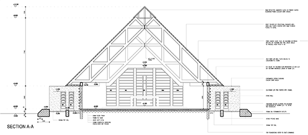
Drawings showing what would be seen if you were to cut a building vertically, like a cake, and look at it from the side. Sectional drawings show the relationship between the different layers, floors and structures.
Shop drawings
These are prepared by the contractor, suppliers or manufacturers showing how pre-fabricated parts should be installed or assembled. They detail out the construction drawings for ready-made items and adapt them to the specific project.
Site plans
Large scale drawings showing the full site and all the features present on it in order to establish the relationship between the various elements. These are required for local council plan submission.
Technical drawings
A broad overall term covering all drawings that illustrate how things are constructed or assembled. Their intention is to clearly show one way to complete the task as opposed to artistic drawings that can be interpreted in a variety of ways. Most drawings prepared during building design and construction are technical drawings.
Tender drawings
A full set of architect drawings together with all the other engineering drawings, specifications and schedules that are submitted to various contractors to price. These form an integral part of the tender procedure.
These architecture drawings form the backbone of most construction projects and are accompanied by many other specific building designs and plans done by the other engineers on the project. Including structural, civil, electrical, mechanical, fire fighting, etc. the quantity and level of detail of these additional drawings depend on the type and complexity of the project.
Address
2.99 Hobourne Hill
Borrowdale
Harare, Zimbabwe
Contacts
Email: info@panarch.info
Phone: +263 (24) 2870 232


